Industrial PID Controller
There are many different real controller structures on the market. Different aplications use different algorithms, so there is no standard PID algorithm. There is even no standard terminology as in literature and product specifications you find terms like "ideal", "parallel", "series", "ISA", "interactive", "non-interactive" and more. Some terms are used equally or similarly others very differently.
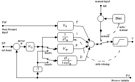
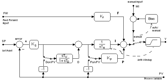
SimApp uses only two designations with regard to the mutual arrangement of the D- and I-channel: Series and parallel. Together with two selectable options (D on PV and P on PV) all knows structures can be achieved.
In the series implementation derivative and integral part are arranged in series, whereas in the parallel implementation D and I are in parallel and so do not interact with each other. In both forms the I and D channels can also be switched to operate on the measurement input (process variable) rather than error signal.
Parallel Form
Serial Form
Features and settings
PonPV
Off: P channel reacts to the error signal (default setting).
On: P channel reacts to the process variable (PV) and so eliminates (or reduces, if D is still present) transfer of set point value discontinuities to control signal.
DonPV
Off: Derivative operates on the set point change (default setting).
On: Derivative works on the process variable (PV) and so prevents impulses on control signal caused by discontinues (jumps) on the reference signal.
Feed-forward action
The feed-forward channel lets the process change independently of process error, and allows faster or earlier reaction to set point disturbances.
Manual mode
In manual mode, all regulation tasks are done through the manual input terminal. A special feature is the bump-less transfer between manual and automatic mode.
When switching from auto to manual mode an automatic bias or offset is applied to the manual input signal, so that the controller's output shows no discontinuities (step changes).
When switching back from manual to auto the output of the integrator is set such that the bump-less transfer is guaranteed also.
In manual mode P and D work as usual but are not used for the output. I channel is stopped and not used either.
First order lowpass Filter in the D-channel
To reduce noise amplification (differentiation noise) of the controller input a low pass filter is combined with the derivative to form a DT1 element.
Output Limitation, Saturation
Limitation of the control signal to prevent overloads.
Anti-Windup-Hold
The integration is stopped and held when the control signal at the saturation input leaves the valid range (upper or lower limit of saturation). As soon as the control signal is reduced, the integrator is released.
Anti-Windup-Reset
If the control signal at the saturation's input exceeds the limit, the integrator's output signal is reduced such that the sum of all action channels (integrator, differentiator, Gain, feedforward) exactly equals the limit (Ymax or Ymin).