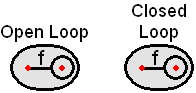
Frequency probe
By means of frequency probes you can define and measure arbitrary subsystems.
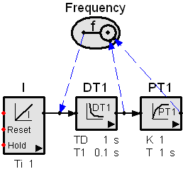
At the output node (left) you can connect one single and at the input node any number of signal lines. The subsystems are defined by the elements laying in between the output and input.
Example: Frequency probe measures subsystems DT1 and DT1-PT1:
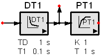
Frequency probes are not mandatory if the system features only one single input. Then, the subsystems are defined by the available outputs. Inputs and outputs are red colored nodes at signal lines and elements having no other connections.
Example: Frequency simulation measures subsystems DT1 and DT1-PT1:
Frequency probes are necessary if you want define nodes as inputs which are painted in black and fed by the outputs other elements.
Example: Input of PT1 is fed by the output of DT1 and hence can not be a system input.
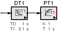
Note: Using frequency nodes causes to ignore all the rest of output nodes.
Each frequency probe causes to open an associated time diagram. Label the probes meaningfully such as the association and meaning is obvious.
Example: